Horizontal member between trusses that support the roof.
Gable wall on a bowstring truss roof system.
One of the common long span trusses for roof support is the bowstring truss photo 1 above.
Buildings spaced very close together or parapet walls designed.
Gable trusses are more expensive than common structural trusses because more lumber is required.
Engineered roof truss systems may be designed to eliminate the need for load bearing walls or change where the bearing walls are located.
A three dimensional structural system without bearing walls composed of interconnected laterally supported so as to function as a complete self contained unit with or without the aids of horizontal diaphragms or floor bracing system.
In this case a single layer of 1 2 gypsum wallboard is attached to the side of a single roof truss in the location shown to provide the required draftstop and area separation.
Bowstring truss roof systems may suffer from a little known phenomenon related to inaccuracies in early industry accepted truss design assumptions.
One big difference with the bowstring truss is that the compressional forces within the top chord act to force the load bearing walls outward as well as downward.
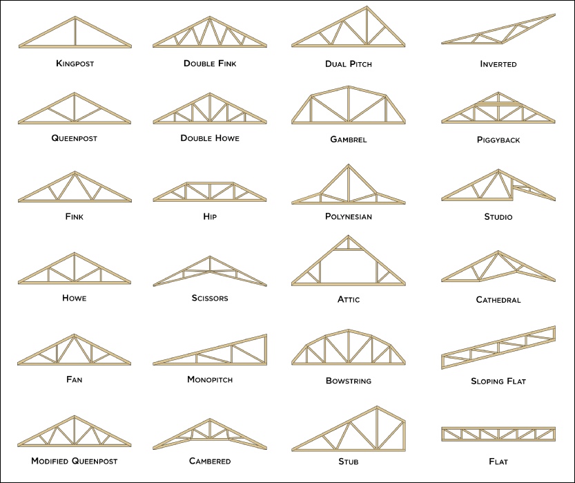
Just as there are many types of roofs with many roof parts there are many different types of roof trusses this extensive article explains through a series of custom truss diagrams the different truss configurations you can use for various roofs.
This type of truss has a straight flat bottom chord that makes attachment of a ceiling simple.
Often times the characteristic arched roof of the bowstring truss building cannot be readily visualized by responding fire companies.
Hip truss systems are very popular throughout the country.
A gable truss sits on the end wall of a structure and has vertical studs every 2 feet or 16 inches.
Figure 17 3 2 shows an alternative roof detail to that in figure 17 3 1 in which the roof trusses are parallel to the wall assembly.
To frame this style roof hip trusses are utilized from the main peak of the building stepping down with a flat top chord.
The flat portion is increased the nearer the truss is to the end wall.
In this design each side of the building has a roof pitch and eave.
For example a gable end truss may be designed with support members that transmit the roof weight load outward to the side walls allowing the end wall directly below it to have breaks or openings in it that would otherwise be impossible.
Floor or roof suspended ceiling system illustration fr system 4 tm ner 392 1991 construction 1 hour rating floor or roof 24 oc min 12 depth 2 layers 1 2 type x gypsum sheathing min 15 32 wh tsc fca 45 02 wh tsc fca 45 04 ga fc5512 nominal 2x3 24 oc min 10 depth truswal metal truss plates 1 layer 5 8 type x gypsum sheathing min 3 4.
While this article focuses on configurations we also have a very cool set of illustrations showcasing the different parts anatomy of roof trusses.

